")
Article Content
- What Are Bubble Columns in Natural Gas Sweetening?
- How Bubble Columns Remove H₂S from Natural Gas
- Types of Bubble Columns Used for Natural Gas Sweetening
- Key Design Parameters for Bubble Columns
- H₂S Scavenger Dosage Calculation for Bubble Columns
- Advantages of Bubble Columns for Natural Gas Sweetening
- Limitations and When NOT to Use Bubble Columns
- Bubble Columns vs Direct Injection vs Amine Sweetening
- Operation, Monitoring & Maintenance Best Practices
- FAQ – Bubble Columns for Natural Gas Sweetening
- Conclusion
Bubble columns (also known as bubble contactors, sparged towers, or flooded contactors) are one of the most efficient and cost-effective methods for H2S removal from natural gas using liquid chemical scavengers. In the oil and gas industry, bubble columns deliver 70–90%+ scavenger utilization — often double that of direct injection — while reliably reducing H₂S to pipeline specs (<4–10 ppmv).
This in-depth guide covers everything process engineers, operators, and procurement teams need to know about bubble columns for natural gas sweetening: how they work, design parameters, scavenger dosage calculations, real-world performance, comparisons to other methods, and best practices. Updated with 2025 industry data from field applications and technical sources.
What Are Bubble Columns in Natural Gas Sweetening?
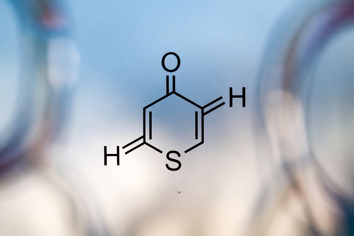
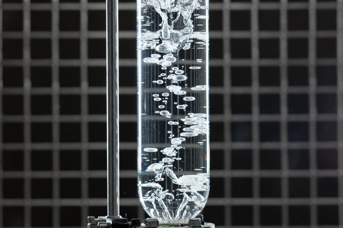
A bubble column is a vertical cylindrical vessel where sour natural gas is introduced at the bottom through a sparger (gas distributor). The gas rises as bubbles through a static or slowly circulating inventory of liquid H₂S scavenger (most commonly 30–50% MEA-triazine or non-triazine alternatives). As bubbles ascend, H₂S transfers into the liquid phase and reacts irreversibly to form non-volatile, water-soluble byproducts.
This intimate gas-liquid contact creates high interfacial area and long residence time (10–60+ seconds), making bubble columns far more efficient than atomized direct injection systems.
Common names in the industry:
- Bubble contactor towers
- Sparged towers
- Flooded contactors
- Scavenger towers / bubbler towers
How Bubble Columns Remove H₂S from Natural Gas
The process relies on mass transfer and chemical reaction:
- Sour gas enters the bottom via sparger → forms fine bubbles
- Bubbles rise through the liquid scavenger inventory
- H₂S dissolves into the aqueous phase (enhanced by high pressure and alkaline pH)
- Chemical reaction occurs (e.g., triazine + H₂S → dithiazine + ethanolamine)
- Sweetened gas exits the top (typically <4 ppm H₂S)
- Spent scavenger is periodically drained and replaced (batch) or continuously bled/topped up
Key performance driver: Bubble size and gas holdup. Smaller bubbles (from fine-orifice spargers) increase interfacial area by 20–50%, boosting mass transfer coefficient (kLa) and overall H₂S removal efficiency.
Types of Bubble Columns Used for Natural Gas Sweetening
| Type | Description | Typical Efficiency | Best Application |
|---|---|---|---|
| Static Batch Contactor | Fixed liquid inventory; batch replacement when spent | 75–90% | Onshore, steady low-moderate H₂S flows |
| Co-Current Dynamic Contactor | Gas + fresh scavenger enter bottom; continuous flow to separator | 80–95% | Higher flows, automated operation |
| Counter-Current Contactor | Gas up, scavenger down; level-controlled | 85–98% | High H₂S or polishing applications |
| Shallow Bubble Column | Low L/D ratio (<5), microbubbles | 80–90% | Offshore, space-constrained |
Key Design Parameters for Bubble Columns
Proper sizing ensures high efficiency and prevents flooding, foaming, or carryover.
Critical Design Factors
- Liquid Height: 3–6 m (10–20 ft) typical — provides sufficient bubble path time
- Superficial Gas Velocity (Ug): 0.05–0.30 m/s (0.15–1 ft/s) — keep below flooding velocity
- Column Diameter: Sized for Ug target; L/D ratio usually >10 for towers
- Sparger Design: Perforated pipe, sieve plates, or membrane diffusers with 1–2 mm holes. Finer holes = smaller bubbles = better performance (but watch for plugging/foaming)
- Gas Holdup: Target 10–25% for optimal mass transfer
- Operating Pressure/Temperature: Higher pressure improves solubility; 80–120°F ideal for triazine kinetics
Rule of thumb: Design for 20–30% overcapacity to handle flow variations.
H₂S Scavenger Dosage Calculation for Bubble Columns
Bubble columns achieve 70–85% utilization (vs. 40–50% in direct injection), so chemical consumption is dramatically lower.
Step-by-step calculation (40% MEA-triazine example):
- H₂S load (lb/day) = MMscfd × ppmv H₂S × 0.0898
- Theoretical scavenger (kg/day) = H₂S kg/day × 8.05
- Actual scavenger at 80% utilization = Theoretical ÷ 0.80
Worked Example: 15 MMscfd gas with 60 ppmv H₂S
- H₂S load = 15 × 60 × 0.0898 ≈ 80.8 lb/day (36.7 kg/day)
- Theoretical = 36.7 × 8.05 ≈ 295 kg/day
- Bubble column actual = 295 ÷ 0.80 = 369 kg/day (~90–100 gal/day at 9.2 lb/gal)
- Daily replenishment after initial fill
Initial inventory: typically 500–2,000+ gallons depending on tower size and desired run time between changes.
Advantages of Bubble Columns for Natural Gas Sweetening
- Up to 2× better chemical efficiency than direct injection → major OPEX savings
- Reliable reduction to <4 ppm H₂S
- Simple design, no moving parts, low maintenance
- Handles variable flows well when properly sized
- Lower total cost of ownership for onshore applications with space available
Limitations and When NOT to Use Bubble Columns
- Higher CAPEX and footprint than direct injection
- Not ideal for very high gas rates (>50–100 MMscfd) or offshore weight/ space constraints
- Potential foaming/solids buildup (monitor pH and spent scavenger)
- Batch systems require planned downtime for changeouts
Bubble Columns vs Direct Injection vs Amine Sweetening
| Parameter | Bubble Column | Direct Injection | Amine Plant |
|---|---|---|---|
| H₂S Removal Efficiency | 70–90%+ scavenger utilization | 40–50% | >99% (regenerative) |
| CAPEX | Medium | Low | High |
| OPEX (chemical) | Low–Medium | High | Medium (energy + amine) |
| Best For | Onshore, 10–500 ppm H₂S, steady flow | Offshore, quick retrofit, low H₂S | High volume, high H₂S/CO₂ |
| Footprint/Weight | Medium–High | Very Low | Very High |
Operation, Monitoring & Maintenance Best Practices
- Continuous H₂S analyzers upstream/downstream
- Monitor spent scavenger pH (>7 preferred) and visual for solids
- Automated level and top-up systems for dynamic contactors
- Regular sparger inspection/cleaning
- Byproduct disposal per local regulations (spent triazine is water-soluble but regulated)
FAQ – Bubble Columns for Natural Gas Sweetening
How much better are bubble columns than direct injection for H₂S scavenger?
Typically 1.6–2× better utilization (70–90% vs 40–50%), cutting chemical costs 40–60%.
What is the typical liquid height in a bubble column scavenger tower?
10–20 ft (3–6 m) for optimal contact time.
Can bubble columns handle CO₂ as well as H₂S?
Yes, but CO₂ slightly increases consumption. Selective scavengers minimize this.
Are bubble columns suitable for offshore platforms?
Shallow or compact designs can work, but direct injection or hybrid systems are often preferred for weight reasons.
Conclusion
Bubble columns remain one of the smartest choices for reliable, economical H₂S removal in natural gas sweetening when conditions favor high contact efficiency and moderate-to-high chemical utilization. With proper design — especially sparger selection and sizing — operators achieve lower OPEX, fewer changeouts, and consistent pipeline compliance.
For new installations or retrofits, start with a detailed dosage calculation and vendor pilot testing on your specific gas composition. Combining bubble column technology with real-time monitoring delivers the best long-term results.
Need help sizing a bubble column system or integrating scavenger dosage calculations for your gas stream? Feel free to contact us.