Article Content
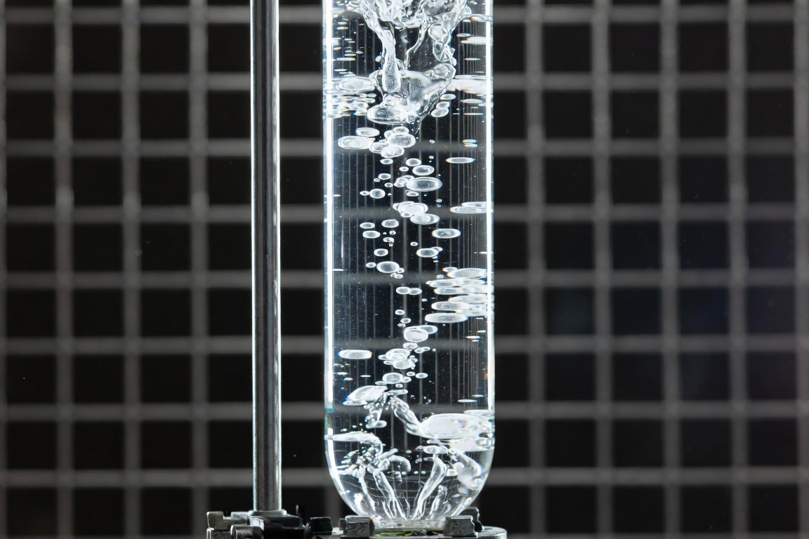
Bubble column reactors (BCRs) are simple, robust vertical cylindrical vessels in which gas is dispersed as bubbles through a liquid (or slurry) phase via a bottom sparger. They excel in gas-liquid contact operations due to high interfacial areas, excellent heat and mass transfer, low operating costs (no moving parts), and suitability for high-pressure or corrosive environments.
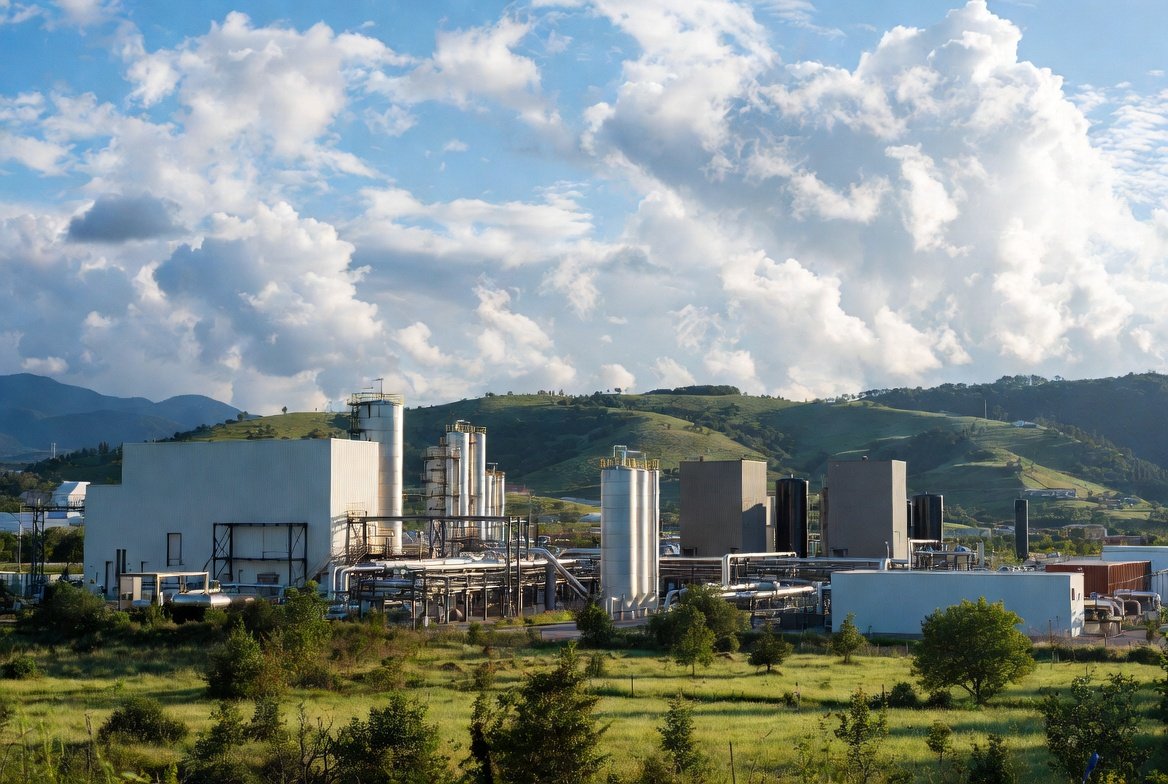
In natural gas processing, BCRs are used for acid gas removal (CO₂/H₂S absorption into aqueous amines or physical solvents), emerging molten-salt/metal pyrolysis for hydrogen production from methane, humidification, or stripping. Although packed or tray columns dominate conventional sweetening, BCRs offer clear advantages in fouling-prone or high-pressure systems.
Sizing a BCR for a given natural gas volumetric flow rate requires balancing hydrodynamics (flow regime, gas holdup εG, bubble size), mass transfer (kLa), residence time, and practical constraints (diameter, height, sparger design). This guide gives you a complete, rigorous, step-by-step methodology based on proven literature (Akita & Yoshida 1973, Shah et al. 1982, Deckwer 1985 and later reviews).
Understanding Bubble Column Dynamics
Superficial Gas Velocity
UG = QG / A
where QG is the actual volumetric gas flow rate (m³/s at operating T and P) and A = π D2 / 4 is the column cross-sectional area.
Typical industrial range: 0.05 – 0.30 m/s.
Flow Regimes
- Homogeneous (bubbly) regime — UG < ~0.03–0.05 m/s: small uniform bubbles (2–6 mm), highest mass-transfer efficiency.
- Transition regime — ~0.03–0.08 m/s.
- Heterogeneous (churn-turbulent) regime — UG > ~0.08–0.10 m/s: larger spherical-cap bubbles, strong liquid recirculation, highest capacity (most common in industrial natural gas columns).
Gas Holdup (εG)
The most widely recommended correlation for design (valid for D > 0.1 m):
εG / (1 − εG)4 = 0.20 × (g D2 ρL / σ)1/8 × (g D3 ρL2 / μL4)1/12 × (UG / √(g D))
(Use 0.25 instead of 0.20 for electrolyte solutions such as amines.)
Interfacial area: a = 6 εG / d32 (Sauter mean bubble diameter d32 ≈ 3–8 mm).
Mass Transfer
Volumetric coefficient kLa typically ranges 0.01–0.25 s⁻¹ and increases with UG and εG.
Column Geometry & Sparger
- Minimum diameter: D > 0.15–0.30 m (holdup and kLa become independent of D above ~0.15 m).
- Aspect ratio (clear liquid height HL / D): 4–8.
- Sparger: perforated plate, 0.5–2% open area, hole diameter 1–3 mm, orifice velocity 10–30 m/s.
Step-by-Step Sizing Procedure
Step 1: Gather Data and Convert Flow Rate
- Natural gas flow (Nm³/h or scfm)
- Operating T, P, composition (calculate actual density ρG and compressibility Z)
- Liquid properties: ρL, μL, σ, diffusivity if known
- Performance target (% removal, required residence time, etc.)
Conversion:
QG = Qstd × (T / Tstd) × (Pstd / P) × (Z / Zstd)
Example used throughout: 5,000 Nm³/h methane at 1 bar, 25°C → QG ≈ 1.389 m³/s.
Step 2: Select Target UG and Regime
- High-capacity natural gas service → heterogeneous regime, start with UG = 0.12–0.20 m/s.
- Maximum mass-transfer efficiency → homogeneous, UG = 0.03–0.06 m/s.
Recommended starting point: UG = 0.15 m/s.
Step 3: Calculate Diameter D
D = √(4 QG / (π UG))
Example: UG = 0.15 m/s → D ≈ 3.43 m (practical industrial size).
Step 4: Estimate Gas Holdup εG
Solve the Akita & Yoshida equation iteratively (or use a simple solver/Excel).
Example result: εG ≈ 0.22.
Step 5: Determine Heights and Residence Time
Choose HL / D = 4–8.
Dispersion height:
Hd = HL / (1 − εG)
Gas residence time:
τG ≈ (Hd · εG) / UG
Example: HL / D = 5 → HL ≈ 17.2 m, Hd ≈ 22 m, τG ≈ 32 s (excellent for most absorption duties).
Step 6: Design Sparger and Ancillaries
- Open area 0.5–2%.
- Pressure drop across sparger typically 0.1–0.5 bar.
- Add 1–2 m disengagement zone above dispersion height.
- Total vessel height ≈ Hd + 2–3 m.
Step 7: Verify & Iterate
Estimate kLa (0.05–0.15 s⁻¹ typical at UG = 0.15 m/s).
Add 10–20% safety margin. For D > 3 m, strongly recommend pilot testing or CFD.
Full Worked Example – 5,000 Nm³/h Natural Gas
- Actual QG = 1.389 m³/s (1 bar, 25°C)
- Target UG = 0.15 m/s (heterogeneous) → Diameter = 3.43 m
- εG ≈ 0.22
- Clear liquid height HL = 17 m (HL/D ≈ 5)
- Dispersion height Hd ≈ 21.8 m
- Total vessel height ≈ 24–25 m (incl. disengagement)
- Estimated dispersion volume ≈ 200 m³ — fully feasible for industrial NG sweetening skid.
(If you prefer homogeneous regime at UG = 0.04 m/s the diameter grows to ~6.65 m but mass transfer efficiency improves significantly.)
Special Considerations for Natural Gas Service
- Pressure effects (common 10–100 bar): higher gas density → smaller bubbles → higher εG and kLa. Always use actual conditions.
- Safety: flammable gas. Design per ASME BPVC / API 521, include rupture disks, flame arrestors, gas detectors, ATEX-rated instrumentation.
- Materials: carbon steel for sweet gas; duplex stainless or lined vessels for sour service (H₂S).
- Foaming: amine solutions foam easily — plan for antifoam injection or special internals.
- Scale-up rules: keep UG and HL/D constant. For large diameters use multiple columns or internals (baffles, draft tubes).
Common Pitfalls to Avoid
- Using standard instead of actual QG
- Poor sparger design causing channeling
- Underestimating back-mixing (BCRs are closer to well-mixed than plug-flow)
- Ignoring pressure effects on hydrodynamics
Final Recommendations
The methodology above, anchored in superficial velocity selection, Akita-Yoshida-type correlations, and proven geometric rules, gives a reliable first-principles design for any natural gas flow rate.
For critical applications always validate with pilot-scale tests (D = 0.1–0.3 m) or detailed CFD. Commercial software (Aspen, ANSYS Fluent with population balance) can refine the design further.
For a general overview of Bubble columns for gas sweetening.
Selected References
- Akita, K., & Yoshida, F. (1973). Gas Holdup and Volumetric Mass Transfer Coefficient in Bubble Columns.
- Shah, Y.T. et al. (1982). Design Parameters Estimations for Bubble Column Reactors.
- Deckwer, W.-D. (1985). Bubble Column Reactors.
- Wilkinson, P.M. et al. (1992). Scale-up criteria.