Article Content
- Understanding Direct Injection of H2S Scavengers
- Choosing the Right Injection Location: Upstream at the Wellhead vs. Gathering Points
- The Critical Role of Contact Time in Scavenger Efficiency
- Temperature: A Key Variable in Reaction Kinetics
- Additional Factors for Injection Optimization
- Best Practices and Implementation Roadmap
- Conclusion: A Data-Driven Approach Delivers Results
To meet stringent sales specifications—often requiring H₂S levels below 4 ppm—operators rely on chemical H2S scavengers to neutralize it effectively, applied via direct injection or bubble columns.
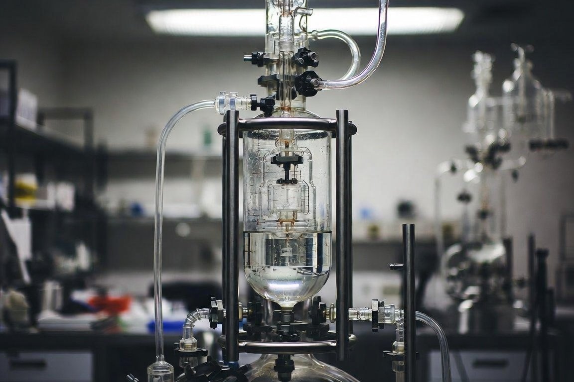
Among the various removal methods, direct injection of liquid H₂S scavengers (commonly triazine-based chemistries like MEA triazine) into gas streams has become a preferred, cost-effective solution for many upstream and midstream operations. Unlike bulky contactor towers or amine units, direct injection requires minimal capital expenditure and can be deployed quickly in space-constrained environments such as offshore platforms or remote well pads.
However, the success of direct injection hinges on one critical decision: where to inject the scavenger. Injecting upstream at the wellhead versus at centralized gathering points can dramatically affect efficiency, chemical consumption, and overall economics. This article explores the best practices for determining optimal injection locations, optimizing the process through key parameters like contact time and temperature, and implementing strategies to maximize performance in gas producing systems. Drawing from industry modeling, field data, and engineering principles, we provide actionable insights for operators seeking to reduce OPEX while ensuring compliance and safety.
Understanding Direct Injection of H2S Scavengers
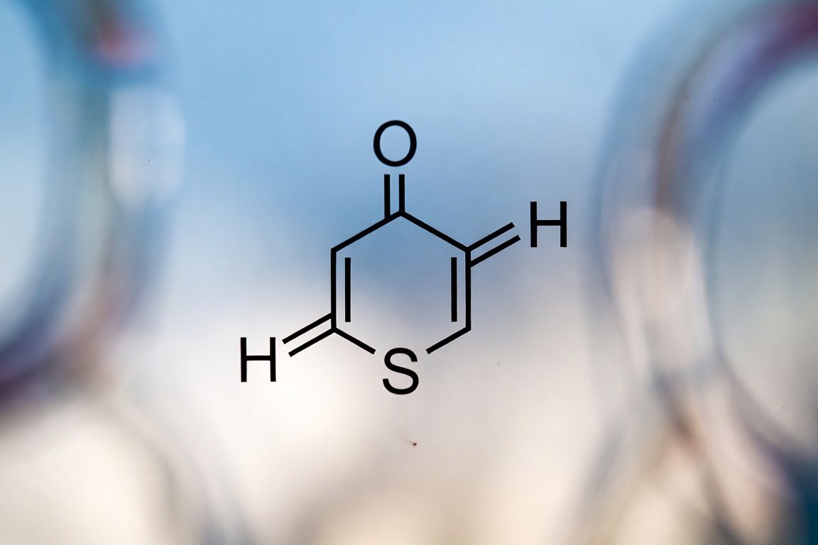
Direct injection involves pumping a liquid scavenger—typically an aqueous solution of triazine or non-triazine alternatives—into the gas flowline or pipeline via specialized quills, atomizing nozzles, or spray systems. The scavenger reacts chemically with H₂S to form non-volatile, water-soluble byproducts that are later separated downstream.
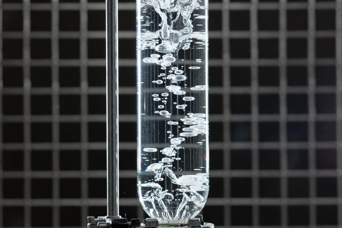
The reaction is mass-transfer limited: H₂S must first dissolve from the gas phase into the liquid scavenger droplets or film before reacting. This makes proper dispersion and sufficient residence time essential. Common applications include injection post-wellhead separators, in gathering lines, or before dehydration units.
While simple in concept, direct injection achieves efficiencies of 40-80% depending on system design—far lower than tower-based methods unless optimized. Key advantages include low CAPEX, flexibility for variable flows, and suitability for low-to-moderate H₂S concentrations (typically <500 ppm). Challenges arise from poor mixing, short contact times, or suboptimal conditions, leading to overtreatment, excessive chemical use, and potential fouling from reaction products.
Choosing the Right Injection Location: Upstream at the Wellhead vs. Gathering Points
The location of injection is the single most influential factor in direct injection performance. Operators must weigh pipeline length, flow dynamics, and operational constraints.
Upstream Injection (Wellhead or Post-Separator): Injecting near the wellhead—after initial water and hydrocarbon separation—offers the longest available contact time in the gathering pipeline. Gas travels through hundreds or thousands of feet of pipe before reaching processing facilities, providing ample residence time for the scavenger to react. Field data shows this approach can reduce chemical consumption by up to 50% compared to centralized injection, as seen in Permian Basin operations where wellhead injection lowered H₂S to 8-10 ppm at sales points while cutting scavenger volumes significantly.
Benefits include better utilization of existing infrastructure, reduced risk of H₂S breakthrough at custody transfer points, and compatibility with multiphase flows. However, challenges include variable wellhead pressures/temperatures, potential for solids or liquids carryover that dilute the scavenger, and the need for multiple injection points across a field. In high-H₂S wells, downhole or umbilical injection may complement topside efforts, but thermal stability limits some chemistries.
Injection at Gathering Points or Centralized Facilities: Centralized injection at gathering stations or headers simplifies logistics—one pump station serves multiple wells. This is ideal for fields with low individual well flows or existing infrastructure. However, if the gathering point is close to the sales meter or processing plant, contact time may be insufficient (often <10 seconds), leading to incomplete reaction and higher dosages.
To mitigate this, operators install retention loops—extended pipe sections or coils downstream of injection—to artificially increase residence time. One case involved a retention loop designed around pad layout, pressure, and temperature data, restoring gas specs while slashing scavenger use. Centralized systems also facilitate real-time monitoring but risk uneven distribution in commingled flows from sour and sweet wells.
Recommendation: Conduct a system-wide review using pipeline modeling software. Prioritize wellhead injection for long gathering lines (>500 ft) or high-velocity flows. Use gathering-point injection only with engineered extensions or when space/logistics dictate. Hybrid approaches—multi-point injection along headers—can balance both worlds.
The Critical Role of Contact Time in Scavenger Efficiency
Contact time is the cornerstone of direct injection optimization. Most triazine scavengers require a minimum of 15-20 seconds for effective reaction, though real-world performance improves with 30-60+ seconds. Insufficient time results in unreacted scavenger passing through, increasing costs and byproduct issues.
Residence time is calculated as pipe volume divided by gas flow rate. Longer pipelines, smaller diameters, or reduced flow velocities extend contact—but velocity must remain high enough for proper mixing. Modeling shows H₂S removal rates increase significantly with pipe length; one simulation demonstrated dose rates dropping as contact time rose in extended lines.
Practical enhancements include:
- Retention Loops or Extended Piping: Custom-designed coils or loops add volume without major rerouting.
- Multi-Pipe Configurations: Splitting flow into parallel smaller-diameter pipes (e.g., 3-6 inch instead of 20 inch) boosts surface area and maintains velocity across turndown ranges.
- Pipe Orientation: Upward flow increases liquid holdup and interfacial area, improving mass transfer over downward or horizontal sections.
Field tests confirm: Systems with inadequate contact (e.g., injection near custody transfer) consumed excessive scavenger until loops were added, achieving specs at lower doses.
Temperature: A Key Variable in Reaction Kinetics
Temperature profoundly influences scavenger performance. Optimal ranges are typically 60-120°F (15-49°C), common in wellhead gas after cooling. At these levels, reaction kinetics are favorable without excessive byproduct formation.
Lower temperatures (<60°F) slow mass transfer and reaction rates, reducing efficiency—critical in winter operations or storage withdrawal gas. Higher temperatures (>120°F, such as post-compression) accelerate initial rates but risk scavenger degradation, corrosive byproducts, or polymerization of dithiazine (from triazines). Some offshore platforms inject into hotter streams successfully but monitor closely for fouling.
CO₂ presence exacerbates temperature effects by lowering pH and competing for scavenger capacity. Site-specific lab testing under actual temperature and pressure is essential before deployment. Non-triazine scavengers may offer wider thermal windows for extreme conditions.
Additional Factors for Injection Optimization
Beyond location, contact time, and temperature, several parameters demand attention:
- Flow Regime and Gas Velocity: Annular-mist flow (liquid film on walls plus entrained droplets) maximizes interfacial area, outperforming stratified flow (liquid pooling at bottom). Target velocities of 10-50 ft/s; higher flows dramatically boost removal rates. Multi-pipe designs prevent regime shifts during turndown.
- Mixing and Injection Hardware: Atomizing quills or nozzles create fine droplets for rapid dispersion. Static mixers or pipe bends aid in short sections. Avoid large-diameter single pipes where poor wetting occurs.
- Pressure and Gas Composition: Higher pressures enhance solubility but must balance with velocity. Water saturation prevents precipitation; sub-saturated gas may require humidification. CO₂ levels increase chemical demand.
- Dosing and Monitoring: Base initial doses on stoichiometry (e.g., ~2 gal triazine per lb H₂S), then refine with real-time H₂S analyzers upstream and downstream. Automated feedback systems minimize waste. Lab bench tests under field conditions validate chemistry selection.
Advanced kinetic-mass transfer models (incorporating flow regime, temperature, and pipe geometry) predict performance accurately, guiding design before installation.
Best Practices and Implementation Roadmap
To optimize:
- Perform a full system audit: Map pipelines, flows, pressures, temperatures, and H₂S profiles.
- Conduct lab and pilot testing for scavenger compatibility.
- Design injection using modeling tools—prioritize multi-pipe or retention features.
- Install injection quills, pumps, and inline analyzers.
- Monitor continuously and adjust dosing dynamically.
- Plan for byproduct handling: Separate spent liquids and dispose per regulations.
Training, maintenance of nozzles, and periodic sampling prevent issues like plugging.
Conclusion: A Data-Driven Approach Delivers Results
Determining the best injection point for H₂S scavengers in direct injection systems is not one-size-fits-all. Upstream wellhead injection generally excels by maximizing contact time in existing pipelines, while gathering-point strategies suit centralized operations with engineered enhancements. Temperature, flow regime, mixing, and real-time monitoring are pivotal to optimization, often reducing chemical costs by 20-50% and ensuring reliable H₂S removal.
By combining engineering modeling, site-specific testing, and continuous optimization, operators can transform direct injection from a basic fix into a highly efficient, low-footprint solution. In an era of tighter regulations and cost pressures, mastering these strategies enhances safety, profitability, and environmental stewardship across gas producing systems.