Article Content
In the rapidly evolving field of gas purification, FeO-based adsorbent media — primarily iron oxide (Fe₂O₃), iron hydroxide (FeOOH or Fe(OH)₃), and hybrid formulations such as iron sponge and commercial products like SulfaTreat® — stand out as highly effective solutions for removing hydrogen sulfide (H₂S) from biogas, natural gas, landfill gas, and industrial off-gas streams. These media operate via chemisorption, where H₂S chemically reacts with the iron oxide to form stable iron sulfides and water, offering superior capacity in moist, low-oxygen environments compared to traditional physical adsorbents.
Properly sizing the adsorbent vessel is critical. An undersized vessel leads to premature breakthrough, frequent media changeouts, and downtime. An oversized vessel wastes capital and increases pressure drop unnecessarily. This in-depth guide walks you through every aspect of vessel sizing for FeO-based media, from fundamental principles to practical calculations and operational considerations. Whether you are designing a new biogas upgrading system or optimizing an existing H₂S removal skid, the methods outlined here will help you achieve >99% removal efficiency while minimizing OPEX.
For a detailed comparison of FeO-based adsorbents versus activated carbon, read our companion article on FeO-Based Adsorbents and Activated Carbon – Comparison at FirstKlaz Technologies.
Understanding FeO-Based Adsorbent Media
FeO-based media are granular or extruded iron oxide/hydroxide materials engineered for high reactivity with H₂S. The primary reaction is:
Fe₂O₃ + 3H₂S → Fe₂S₃ + 3H₂O (or similar for hydroxide variants: 2Fe(OH)₃ + 3H₂S → Fe₂S₃ + 6H₂O).
In the presence of trace oxygen, the spent media can be partially regenerated to elemental sulfur, extending service life. Typical capacities range from 200–710 g H₂S per kg of media, depending on formulation, moisture content, and operating conditions. Bulk density is usually 40–55 lb/ft³ (640–880 kg/m³) for loose fill, with particle sizes between 3–20 mm to balance surface area and pressure drop.
These media excel in wet-gas applications (relative humidity >50%) where activated carbon may underperform due to competitive water adsorption. They are non-regenerable in most high-H₂S scenarios but offer low capital cost and simple disposal as non-hazardous waste (subject to local regulations). Common applications include biogas plants (H₂S inlet 500–5000 ppm), natural gas sweetening, and wastewater odor control. See our manufacturing overview at Manufacturing Iron Oxide / Hydroxide-Based Adsorbents for insight into how particle size and porosity are optimized during production.
Key Design Parameters for Vessel Sizing
Accurate sizing begins with a complete process data sheet. Essential inputs include:
- Gas flow rate (Q): Typically in MMSCFD, scfm, or m³/h. Convert to actual cubic feet per minute (ACFM) using operating temperature and pressure.
- H₂S concentration: Inlet ppmv (parts per million by volume). Calculate daily mass load as (flow × concentration × molecular weight factor).
- Operating conditions: Temperature (usually 60–120 °F / 15–50 °C), pressure (near atmospheric for biogas), and moisture (saturated preferred).
- Desired service life: Days or months between changeouts (aim for 3–12 months).
- Media properties: Capacity (g H₂S/kg), bulk density, and allowable superficial velocity (typically 5–10 ft/min to avoid channeling or excessive pressure drop).
- Removal target: >99% H₂S removal with safety factor of 1.5–2.0 on capacity.
Empty bed contact time (EBCT) should be 60–300 seconds for FeO media to allow complete reaction. Superficial velocity must stay below 10 ft/min (0.05 m/s) for proper gas–solid contact while exceeding ~2 ft/min to prevent channeling. Pressure drop is kept under 0.5–2 psi/ft using the Ergun equation (detailed later).
Step-by-Step Vessel Sizing Procedure
Follow this rigorous methodology, adapted from industry standards for iron sponge systems and fixed-bed adsorber design (Cornell University Dairy Environmental Systems Program guidelines).
1. Calculate Daily H₂S Mass Load
Daily H₂S load (lb/day) = Q (MMSCFD) × H₂S (ppmv) × 0.0898 (conversion factor at 60 °F, 14.7 psia).
Example: 0.5 MMSCFD at 2000 ppm H₂S = 89.8 lb/day H₂S.
2. Determine Required Media Mass
Media mass (lb) = (Daily load × Desired days) / (Media capacity lb H₂S/lb media) × Safety factor (1.5–2.0).
Using 0.3 lb H₂S/lb media, 90-day life, and safety factor 1.75: Media = (89.8 × 90) / 0.3 × 1.75 ≈ 47,145 lb.
3. Calculate Bed Volume
Bed volume (ft³) = Media mass / Bulk density.
At 45 lb/ft³: Volume ≈ 1,048 ft³ total.
4. Select Vessel Diameter (Velocity Constraints)
Minimum diameter ensures adequate gas contact and limits H₂S deposition rate.
Use iron-sponge design equations (U.S. customary units):
d_min (inches) = √[360 × Q_g × T × Z / P] (velocity limit ≈10 ft/min)
Where Q_g = gas flow (MMSCFD), T = °R, Z ≈1, P = psia.
Second constraint (H₂S deposition ≤15 grains/min/ft²):
d_min (inches) = √[5.34 × 10⁶ × Q_g × MF]
MF = mole fraction H₂S (ppm / 1,000,000).
Choose the larger d_min. Maximum diameter to avoid channeling:
d_max = √[1,800 × Q_g × T × Z / P²].
For the example (0.5 MMSCFD, 70 °F, 14.7 psia): d_min (velocity) ≈ 81 inches; d_min (deposition) ≈ 73 inches → use 84-inch (7 ft) diameter vessels. For 1,048 ft³ total volume, use two vessels in lead-lag (each ~524 ft³).
5. Determine Bed Height (Contact Time)
Minimum height H (ft) ≥ 3,600 × Q_g × T × Z / (P × d²) for 60-second contact time.
Ensure H ≥ 5 ft and L/D ratio ≥ 3 for uniform flow. For 84-inch ID vessels: each bed height ≈ 27 ft (excellent contact time ≈ 120 seconds per vessel).
6. Verify Pressure Drop
Use the Ergun equation:
ΔP/L = [150μ(1-ε)²V / (ε³d_p²)] + [1.75ρ(1-ε)V² / (ε³d_p)]
Where μ = viscosity, ε = void fraction (~0.4), V = superficial velocity, d_p = particle diameter. Target total ΔP < 5–10 psi across the bed.
7. Vessel Configuration
Use two (or more) vessels in lead-lag series for continuous operation. When the lead vessel approaches breakthrough (monitor outlet H₂S), switch to lag and replace lead media offline. For larger flows, add parallel trains.
Example Calculation
0.5 MMSCFD biogas, 2000 ppm H₂S, 70 °F, 14.7 psia.
d_min (velocity) ≈ 81 inches → use 84-inch vessels (two in lead-lag).
Total bed volume ≈ 1,048 ft³ → each vessel ≈ 27 ft bed height.
Contact time ≈ 120 seconds per vessel. Perfect for 3-month life with 1.75 safety factor.
Vessel Design and Construction Considerations
Vessels are typically vertical carbon steel or 304/316 stainless steel towers (ASME Section VIII compliant) with epoxy or rubber lining to resist H₂S corrosion. Include:
- Top and bottom manways for media filling/removal.
- Gas inlet diffuser and outlet collector to prevent media fluidization.
- Drain ports for condensate.
- Pressure relief and sampling ports.
- Internal supports and screens (316 SS mesh).
For high-pressure applications (>50 psig), use ASME-rated pressure vessels. Fiberglass-reinforced plastic (FRP) is acceptable for low-pressure biogas systems.
Operational, Safety, and Maintenance Best Practices
Pre-moisten media to 20–40% moisture before startup. Maintain gas saturation to prevent drying and dusting. Monitor inlet/outlet H₂S daily with portable analyzers. Change media when outlet reaches 50–100 ppm (or per warranty).
Safety: H₂S is toxic and flammable. Use SCBA during changeouts. Spent media may be pyrophoric if dried; keep wet during removal. Dispose as non-hazardous landfill in most jurisdictions.
Regeneration (if oxygen present) can double life but requires careful air injection to avoid hotspots. Annual inspection for channeling or compaction is recommended.
Advanced Considerations and Modeling
For critical applications, perform lab-scale breakthrough testing or use software (Aspen Adsorption or custom MATLAB models) to predict mass transfer zone (MTZ) length. Scale-up factor is typically 1.2–1.5 from lab to field. Temperature swings above 120 °F reduce capacity; below 40 °F slow kinetics. Co-contaminants (siloxanes, VOCs) may require upstream polishing.
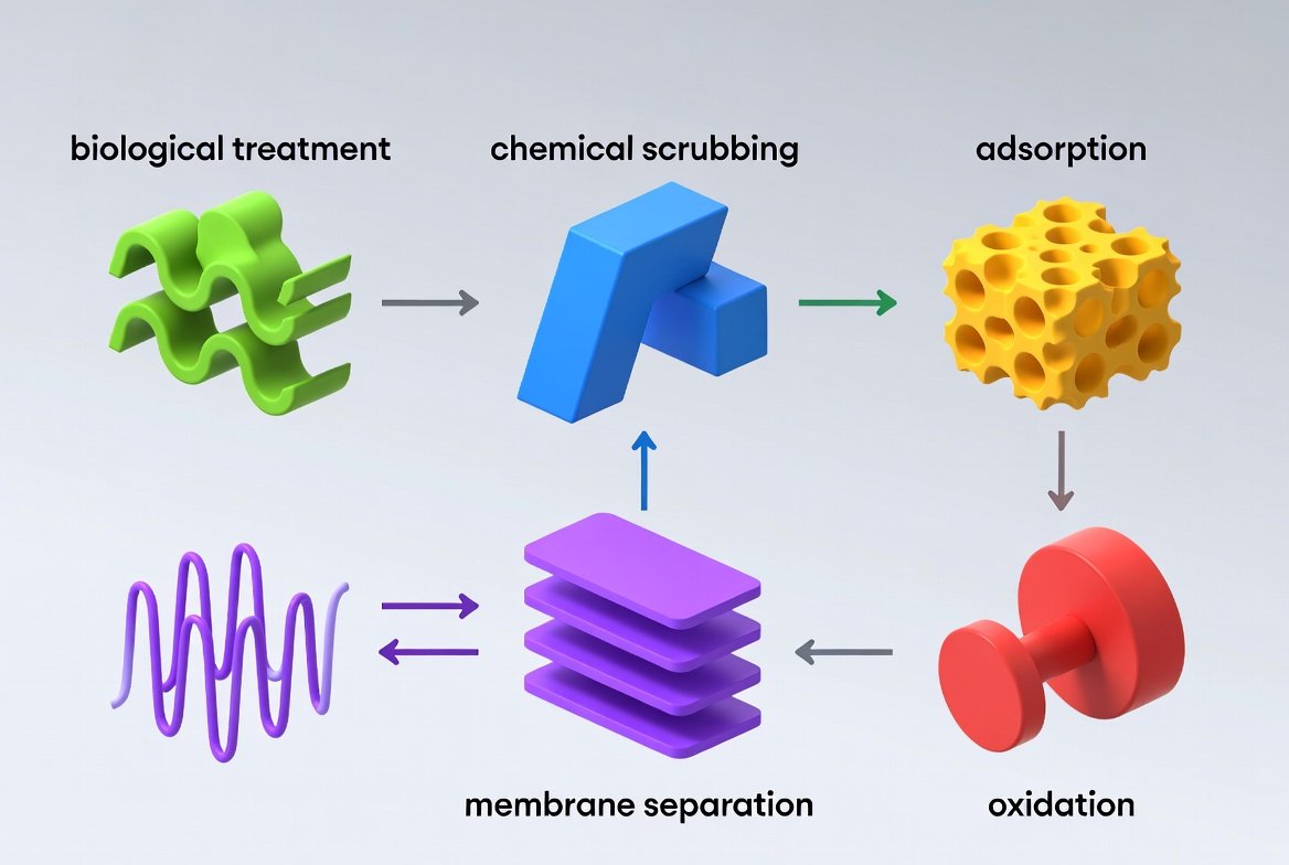
Hybrid systems combining FeO media with impregnated carbon or biological scrubbers further optimize economics.
Conclusion
Sizing an FeO-based adsorbent vessel is both science and art. By methodically calculating load, applying velocity and contact-time constraints, and incorporating safety factors, engineers can design reliable, cost-effective H₂S removal systems that last years with minimal intervention. The formulas and procedures in this guide, drawn from decades of iron-sponge and SulfaTreat field experience, provide a solid foundation. Always validate with media supplier data sheets and consider a pilot test for unique gas compositions.