Article Content
Amine sweetening plants, also known as amine gas treating or acid gas removal units, are critical components in natural gas processing, refinery operations, and petrochemical facilities. These plants remove corrosive and toxic acid gases—primarily hydrogen sulfide (H₂S) and carbon dioxide (CO₂)—from sour gas streams to produce “sweet” gas that meets pipeline specifications, environmental regulations, and downstream process requirements. Without effective sweetening, acid gases can cause corrosion in pipelines and equipment, pose safety hazards, and contribute to emissions of sulfur compounds.
The process relies on chemical absorption using aqueous solutions of alkanolamines. Lean amine enters an absorber tower and chemically binds with acid gases. The rich amine is then regenerated in a stripper column using heat, releasing the acid gases for further processing (often in a sulfur recovery unit). While the technology dates back to the 1930s (e.g., the Girbotol process), modern amine units are highly optimized for energy efficiency, selectivity, and minimal solvent losses.
This article provides a foundational overview of amine sweetening plants, with a strong emphasis on basic engineering calculations for amine circulation rate, reboiler duty, amine consumption, and related parameters. These calculations are essential for preliminary design, troubleshooting, and optimization. We will use industry-standard rules of thumb, molar balances, and examples drawn from established references like the GPSA Engineering Data Book and Laurance Reid Gas Conditioning conferences.
The Amine Sweetening Process: Step-by-Step Overview
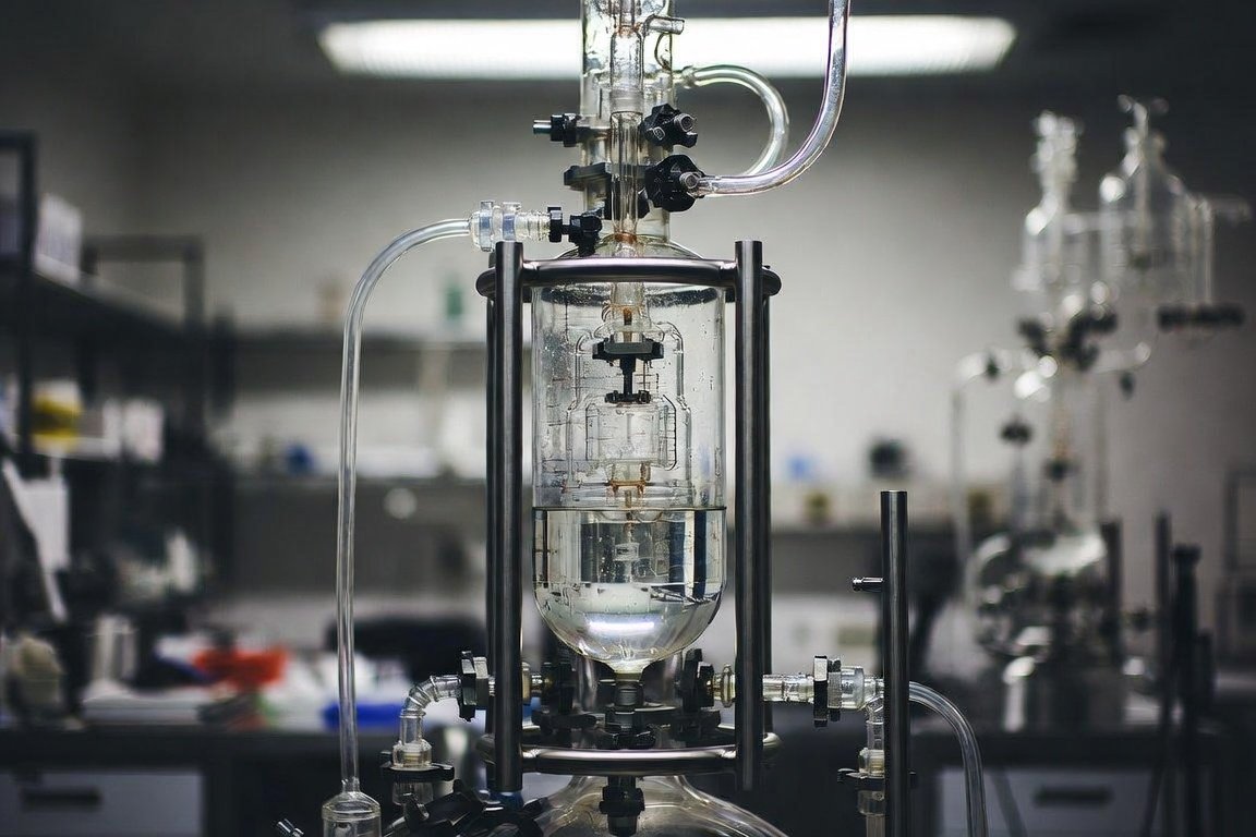
A typical amine sweetening unit consists of several interconnected vessels and heat exchangers. Sour gas (containing H₂S and CO₂) first passes through an inlet separator to remove free liquids, solids, and hydrocarbons. The gas then enters the bottom of the absorber (contactor) tower, flowing upward counter-current to a descending stream of lean amine solution (typically 15–55 wt% amine in water).
In the absorber, acid gases react reversibly with the amine:
RNH₂ + H₂S ⇌ RNH₃⁺ + HS⁻ (for primary/secondary amines)
RNH₂ + CO₂ + H₂O ⇌ RNH₃⁺ + HCO₃⁻
The sweetened gas exits the top of the absorber, while rich amine (loaded with acid gases) leaves the bottom. The rich amine is flashed in a high-pressure flash drum to recover dissolved hydrocarbons, then preheated in a lean/rich heat exchanger before entering the regenerator (stripper) column.
In the regenerator, heat from a reboiler (usually low-pressure steam) reverses the reactions, stripping the acid gases overhead. The overhead vapor is cooled in a condenser, with reflux returned to the column. Regenerated lean amine is cooled, filtered, and pumped back to the absorber. Acid gas from the regenerator overhead is typically routed to a Claus sulfur recovery unit or flared.
Key ancillary equipment includes mechanical and activated carbon filters to control foaming and degradation products, a reclaimer (for MEA systems), and trim coolers. The process operates at absorber pressures of 100–1000+ psig and regenerator pressures of 10–30 psig.
Common Amines and Their Properties
Selection of the amine solvent depends on acid gas composition, selectivity requirements, energy costs, and corrosion concerns. The three most common alkanolamines are:
| Amine | Type | Typical Concentration (wt%) | Acid Gas Loading (mol/mol) | Key Advantages | Key Disadvantages |
|---|---|---|---|---|---|
| Monoethanolamine (MEA) | Primary | 15–25 | Lean: 0.01–0.1; Rich: 0.3–0.5 | High reactivity; good for low-pressure CO₂ removal | High regeneration energy; corrosive; degrades easily |
| Diethanolamine (DEA) | Secondary | 25–35 | Lean: 0.01–0.1; Rich: 0.4–0.6 | Less corrosive than MEA; lower energy than MEA | Slower kinetics with CO₂; higher viscosity |
| Methyldiethanolamine (MDEA) | Tertiary | 35–55 | Lean: 0.005–0.05; Rich: 0.4–0.8 | Selective H₂S removal; low energy; high loading capacity | Slower CO₂ reaction (needs activator for bulk CO₂) |
MDEA is increasingly preferred for its lower reboiler duty and selectivity toward H₂S over CO₂. Blends (e.g., MDEA + piperazine) are common for tailored performance.
Basic Calculations in Amine Sweetening Design
Accurate calculations of circulation rate, reboiler duty, and solvent makeup are fundamental to sizing equipment, estimating operating costs, and ensuring the unit meets sweet gas specifications (typically <4 ppm H₂S and <2% CO₂ for pipeline gas).
1. Amine Circulation Rate
The amine circulation rate is determined primarily from a material balance on the acid gases. The goal is to provide enough amine moles to achieve the required delta loading (rich loading minus lean loading) while meeting overhead specifications.
Basic Molar Balance Equation:
Amine circulation (mol/min) = Acid gas to be removed (mol/min) / ΔLoading (mol acid gas / mol amine)
Where ΔLoading = rich loading – lean loading (typical values: 0.3–0.5 mol/mol for MEA/DEA; up to 0.7 for MDEA).
To convert to volumetric flow (gpm or m³/h):
Circulation rate (gpm) = [Amine mol/min × MW_amine] / [Density (lb/gal) × 8.34 × (wt% amine / 100) × 60 / mol fraction adjustment]
Simplified Rule-of-Thumb Formula (GPSA-style for preliminary estimates):
gpm amine ≈ [Q_g × (y_H2S + y_CO2) × 1000 × F] / [C × L × 0.35]
Where Q_g = gas flow (MMscfd), y = mole fraction acid gas, F = factor (≈2.5–3.5 depending on amine), C = amine concentration (wt%), L = loading pickup (mol/mol).
Example Calculation: 80 MMscfd sour gas at 100°F/1000 psia containing 7% CO₂ and 3% H₂S (total acid gas = 10%). Use 27 wt% DEA, ΔLoading = 0.58 mol/mol (75% approach to equilibrium).
- Acid gas flow = 80 × 0.10 × (10⁶ scf/day) / 379.5 scf/lb-mol ≈ 21,080 lb-mol/day or 14.63 lb-mol/min.
- Amine required = 14.63 / 0.58 ≈ 25.2 lb-mol DEA/min.
- DEA solution gpm (density ≈8.49 lb/gal, 27 wt%) ≈ 1,194 gpm (after energy balance iteration for rich temperature ≈158°F).
This rate ensures the absorber achieves equilibrium approach. Iterative absorber energy balance (heat of reaction + gas cooling = solvent heating) is used for precision. Lower lean amine temperature (e.g., 10°F approach to gas dew point instead of strict 10°F rule) can reduce required circulation by 10–20%.
2. Reboiler Duty
Reboiler duty is the largest energy consumer in the unit (typically 50–70% of operating costs). It supplies sensible heat, heat of desorption (reverse reaction), and stripping steam to regenerate the amine.
Rule-of-Thumb Steam Ratio: 0.8–1.2 lb steam per gallon of amine circulated (or 0.09–0.12 kg/L). Optimized values can be as low as 0.09–0.10 kg/L for 10–15% energy savings.
Component Breakdown of Reboiler Duty (Q_reb in Btu/hr):
Q_reb = Q_sensible + Q_desorption + Q_vaporization
- Sensible heat: m_amine × C_p × ΔT (rich amine to reboiler temperature, typically +20–40°F).
- Desorption heat: ≈ 500–800 Btu/lb acid gas removed (511 Btu/lb H₂S, 653 Btu/lb CO₂ for MEA/DEA).
- Vaporization (stripping steam): Latent heat for 1–2 mol H₂O per mol acid gas (reflux ratio ≈1.5–4:1).
Typical Range: 800–1,200 Btu/gal amine circulated (MDEA is lower: 600–900 Btu/gal due to weaker bonds). For the 1,194 gpm example above: ≈ 58.9 MMBtu/hr total reboiler duty.
Optimization tip: Increasing regenerator pressure (to 3–5 bar) reduces duty by 10–25% by lowering water vaporization requirements, but watch thermal degradation (<260°F for most amines).
3. Amine Consumption and Makeup Requirements
Amine losses occur via vaporization, entrainment, degradation (thermal/chemical forming heat-stable salts), and mechanical carryover. Makeup maintains inventory and solution strength.
Typical Loss Rates (per MMscf gas processed):
- MEA: 1–3 lb amine / MMscf (higher due to degradation)
- DEA: 0.5–1.5 lb / MMscf
- MDEA: 0.1–0.5 lb / MMscf (lowest)
Water makeup is usually higher (due to evaporation in regenerator overhead) and is added to maintain concentration.
Estimation Formula for Makeup:
Daily amine makeup (lb/day) = Gas flow (MMscfd) × Loss rate (lb/MMscf) × 24
Plus additional for reclaimer bottoms purge (MEA systems). Foaming, high velocities (>3 ft/s in rich lines), and poor filtration increase losses. Activated carbon filters (1–10% of flow) and mechanical filters (10-micron) are critical for minimizing consumption.
Other Key Calculations
- Lean/Rich Heat Exchanger Duty: Typically recovers 60–70% of reboiler heat. Rich-side outlet limited to ≤210°F (99°C) to avoid acid gas breakout and corrosion.
- Tower Sizing (Diameter): Use flooding velocity correlation: U_f = C_sb × √[σ(ρ_L – ρ_G)/ρ_G]. Design at 60–75% of flood.
- Pumping Power: P = Q × ΔP / η (rich and lean pumps).
Modern simulators (e.g., ProMax, Aspen) refine these with equilibrium data, but hand calculations provide excellent first-pass estimates.
Operational Considerations and Best Practices
Successful operation requires controlling foaming (via antifoam and filtration), corrosion (pH 8–10, proper metallurgy), and hydrocarbon carryover. Monitor lean loadings, pressure drops, and solution color/foaming tendency. Rules of thumb (e.g., 10°F temperature approach, 1 lb/gal steam) are starting points—case-specific optimization can reduce reboiler duty by 15–30%.
Environmental notes: Acid gas is recovered and converted to elemental sulfur, minimizing SO₂ emissions. Amine degradation products must be disposed of properly.
Conclusion
Amine sweetening plants are efficient, proven systems for acid gas removal, but their success hinges on sound basic calculations. Accurate determination of circulation rate ensures adequate absorption capacity, while optimized reboiler duty and minimal amine consumption control operating expenses (often millions annually). By understanding molar balances, loading limits, and energy components, engineers can design, operate, and troubleshoot these units effectively. For detailed site-specific design, always validate with process simulation software and vendor data.