Article Content
This article provides a comprehensive, unbiased overview of hydrogen sulfide (H₂S) in landfill gas (LFG). It covers formation mechanisms, operational and regulatory impacts, removal technologies, design factors, and field practices at municipal solid waste (MSW) and construction-and-demolition (C&D) landfills that flare gas, generate power, or produce pipeline-quality renewable natural gas. The discussion is based on process engineering principles and typical plant constraints, not on vendor marketing claims. Biogas from purpose-built digesters is treated only where the comparison clarifies why landfill gas behaves differently.
Why Landfill Gas Is a Distinct H₂S Problem
Landfill gas is not simply another biogas stream. Typical raw LFG contains 45–60% methane, 40–55% carbon dioxide, nitrogen and oxygen from air intrusion, water vapor near saturation, siloxanes, volatile organic compounds, and reduced sulfur species. H₂S is the dominant reduced sulfur compound, but mercaptans and organic sulfides are often present at lower levels.
Concentrations vary over a wide range. Many MSW landfills operate between 20 and 500 ppmv H₂S. C&D landfills and MSW cells that accepted large quantities of gypsum drywall routinely measure 1,000–5,000 ppmv, with documented peaks above 10,000 ppmv. Unlike a well-controlled anaerobic digester, a landfill is a heterogeneous, poorly mixed reactor whose gas quality changes with waste age, moisture, cover integrity, wellfield vacuum, and the sulfate inventory in the waste mass.
That variability drives both the odor problem at the fence line and the mechanical problem at the energy plant. Reciprocating engines, turbines, and boilers convert H₂S to sulfur dioxide. Even a few hundred ppmv H₂S shortens oil life, corrodes aftercoolers and exhaust components, and poisons oxidation catalysts used for CO and VOC control. Pipeline-quality renewable natural gas (RNG) specifications typically require H₂S below 4 ppmv and often below 1 ppmv, so LFG-to-pipeline projects cannot skip dedicated sulfur removal.
How H₂S Forms Inside a Landfill
The principal pathway is dissimilatory sulfate reduction. Sulfate-reducing bacteria (SRB) use sulfate as a terminal electron acceptor under anaerobic conditions and produce H₂S as a metabolic product:
SO₄²⁻ + organic matter → H₂S + CO₂ + HCO₃⁻ + biomass
The largest sulfate source in modern landfills is gypsum drywall (calcium sulfate dihydrate). Gypsum is abundant in C&D debris and is also present in MSW from renovation waste. Other contributors include organic sulfur in food waste and sludges, sulfate in leachate recirculation, and, in some regions, coal combustion residuals or industrial wastes co-disposed with MSW.
SRB activity is favored by:
- Anaerobic conditions once oxygen is depleted in the waste mass
- Moisture near field capacity, including leachate recirculation
- Near-neutral pH and available organic carbon
- Temperatures in the mesophilic range typical of active cells
H₂S generation is not constant. Fresh, wet, gypsum-rich cells produce spikes. Older methanogenic cells often run lower once the sulfate inventory is depleted. Air intrusion can suppress SRB locally but dilutes methane. Cover maintenance, wellfield balancing, and limits on gypsum disposal reduce the load on any downstream unit; they rarely remove the need for gas-phase treatment when LFG is used as fuel.
Operational, Environmental, and Regulatory Drivers
Odor is the most visible driver. H₂S is detectable at low parts-per-billion levels. Community complaints, especially from C&D landfills, have triggered consent orders, additional monitoring, and in some cases restricted waste acceptance. Worker exposure at wells, condensate knockouts, and blower skids is a second driver. Olfactory fatigue makes odor an unreliable warning property above roughly 100 ppmv, so fixed and personal monitors are required.
Equipment protection is the economic driver for LFG-to-energy sites. Sulfur in the fuel increases acid dew-point corrosion in exhaust systems and raises the sulfur content of engine oil. Catalyst vendors set strict sulfur limits, and unplanned catalyst replacement is often more expensive than a correctly sized H₂S bed. Flares convert H₂S to SO₂; where ambient SO₂ or odor rules are tight, flare-only operation is no longer sufficient.
U.S. federal landfill gas rules require collection and control but do not set a single raw-gas H₂S limit. State air permits, odor rules, and RNG interconnection tariffs do. In Canada, provincial odour and ambient objectives plus renewable-fuel rules set the practical targets. In every case the engineering task is the same: cut H₂S to what the end use and the neighbors will accept.
Technology Options for LFG H₂S Removal
No single process is optimal at every concentration, flow, and product specification. The options used in practice fall into five groups.
Solid adsorbents (iron oxides, iron hydroxides, mixed metal oxides, impregnated carbon)
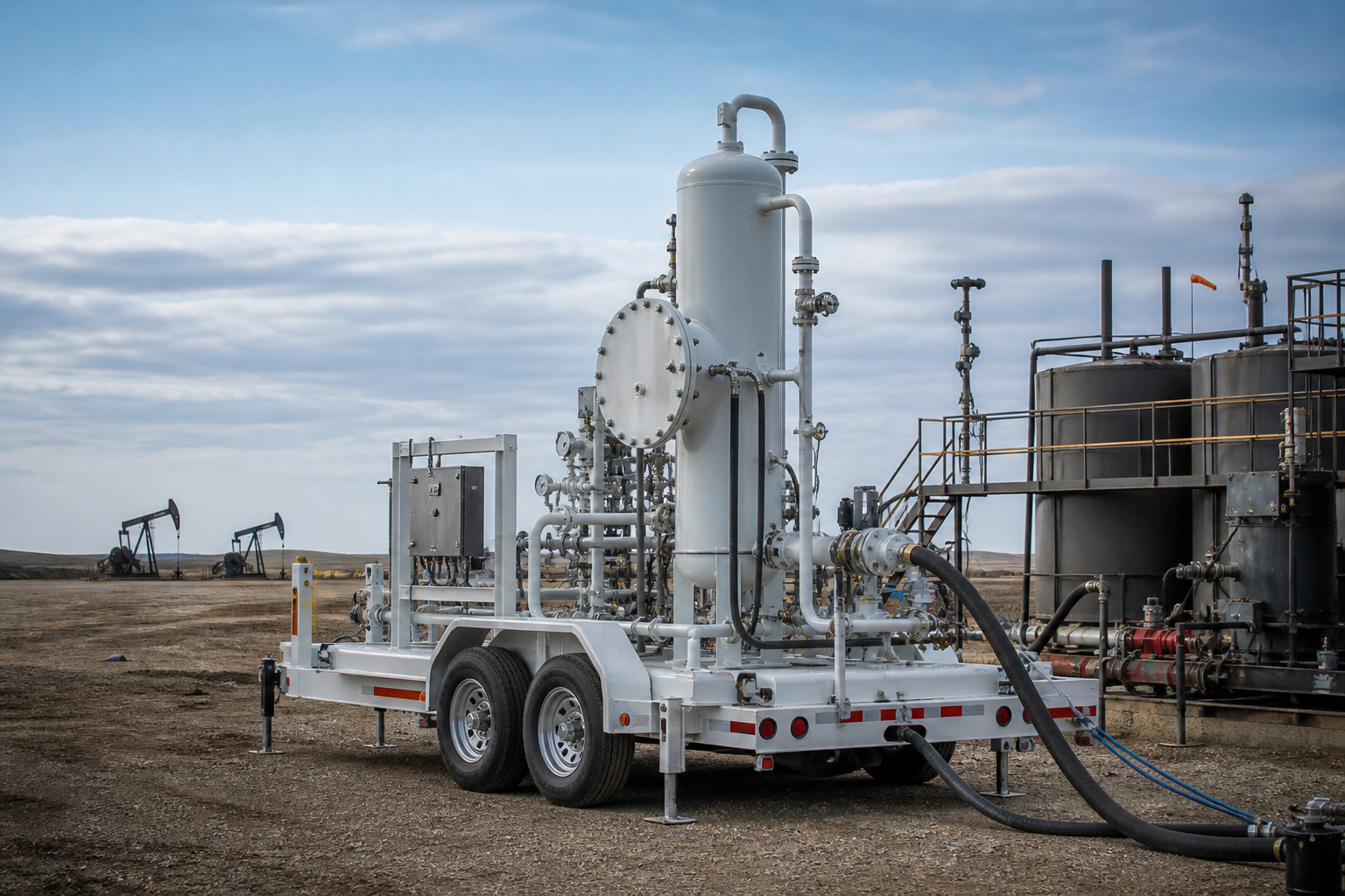
Fixed-bed adsorbers charged with iron-based media are the most common LFG treatment package for small and mid-size sites. H₂S reacts with iron(III) oxides or hydroxides to form iron sulfides. Some media can be partially regenerated by controlled air exposure, converting FeS back toward Fe₂O₃ and elemental sulfur; others are operated as non-regenerable beds and replaced when the outlet H₂S breaks through.
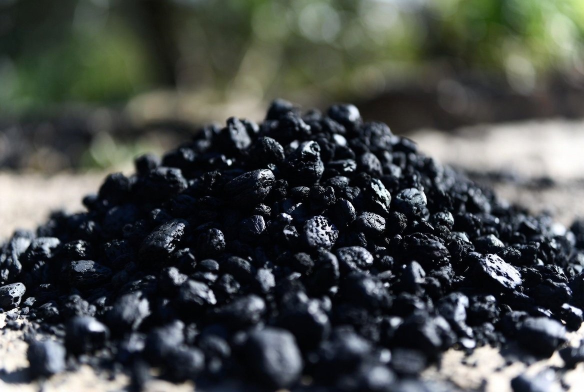
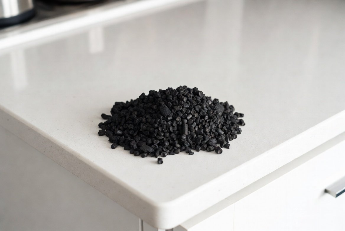
Advantages are simple operation, no liquid effluent, and a good fit for 50–2,000 ppmv at typical wellfield or plant flows. Limitations are rising pressure drop, spent-media handling, heat if on-site regeneration is used, and weak economics at very high continuous sulfur load. Caustic-impregnated or catalytic carbon is used to polish to sub-ppm levels or to combine H₂S and siloxane duty. Carbon costs more per kilogram of sulfur and is sensitive to moisture and heavy hydrocarbons.
Biological systems (biotrickling filters and bioscrubbers)
Sulfide-oxidizing bacteria convert H₂S to elemental sulfur or sulfate under controlled oxygen and nutrient conditions. Biotrickling filters (BTFs) use packed towers with recirculating liquid; bioscrubbers absorb H₂S into a liquid that is oxidized in a separate bioreactor. These systems perform well on continuous LFG streams in the mid-to-high ppmv range and produce a sulfur slurry or sulfate blowdown rather than a solid spent adsorbent.
Biological units need stable temperature, pH, and oxygen control. They are less forgiving of sudden H₂S spikes and of long shutdowns than a simple media bed. When operated correctly they achieve high removal with low chemical consumption, which is attractive for sites with multi-year energy contracts.
Liquid redox and chelated-iron processes
Aqueous processes that oxidize absorbed H₂S to elemental sulfur using a regenerated iron chelate (or a biological liquid-redox analogue) are used when sulfur production is large enough to justify a circulating liquor system. These units can treat high H₂S loadings and produce a salable or disposable sulfur cake. Capital cost, foaming, and chelate degradation are the usual constraints. They are more common at large LFG plants and at industrial sites than at small MSW landfills.
Chemical scrubbing
Caustic or oxidative wet scrubbers (sodium hydroxide, sodium hypochlorite, hydrogen peroxide, or proprietary oxidizers) absorb H₂S into a liquid. They handle peaks well and can be started quickly. Chemical consumption and liquid waste become expensive at sustained high sulfur loads. They are often used as a guard or peak-shaving stage rather than as the sole process on a high-sulfur C&D landfill.
In-situ and wellfield measures
These are not gas-plant technologies, but they change the inlet. Restricting gypsum disposal, improving intermediate and final cover, balancing well vacuum to limit air intrusion without starving collection, and managing leachate recirculation all reduce H₂S generation or leakage. Iron-salt addition to leachate or waste has been used to precipitate sulfide in situ. These measures complement, rather than replace, a gas treatment system when LFG is recovered for energy.
| Technology | Typical inlet H₂S | Typical outlet | Strengths | Limitations | Best fit |
|---|---|---|---|---|---|
| Iron-based adsorbent beds | 20–2,000 ppmv | <4 to <50 ppmv | Simple, no liquid waste, modular | Media changeout, ΔP, weak at very high load | Most MSW LFG-to-energy sites |
| Impregnated / catalytic carbon | Low–mid ppmv | <1–4 ppmv | Polishing, combined siloxane duty | Cost per kg S, moisture sensitivity | RNG interconnect polish |
| Biotrickling filter / bioscrubber | 100–5,000 ppmv | <10–50 ppmv | Low chemical use, continuous duty | Biological lag, utilities, blowdown | Stable high-flow plants |
| Liquid redox / chelated iron | 500–20,000 ppmv | <10 ppmv | High sulfur capacity, sulfur product | Capex, liquor management | Large or high-H₂S plants |
| Oxidative / caustic scrubber | Peaks and mid-range | <10 ppmv | Fast response, peak handling | Chemical and effluent cost | Guard bed or C&D spikes |
Design and Operating Considerations
Inlet characterization is the first design input and the one most often skipped. One grab sample is not a design basis. Measure H₂S across seasons, after C&D campaigns, and after cover or wellfield changes. Flow changes as wells are added and barometric pressure swings. Oversizing a bed for a short peak wastes media; undersizing for the 90th-percentile load causes early breakthrough.
LFG leaves the wellfield near saturation. Knockouts, coalescers, and cooling keep liquid water from channeling a packed bed or flooding BTF packing. Siloxanes and heavy VOCs occupy carbon sites and can create hot spots on catalytic carbon. Packed-bed ΔP of 10–30 inches of water column at end of life is common; vessel diameter, particle size, and lead-lag beds keep that load within blower capacity and allow changeout without a full outage.
Spent iron media is often non-hazardous but still requires documented disposal or regeneration. Biological and liquid-redox units produce sulfur solids and a saline or sulfate blowdown. Disposal cost belongs in the lifecycle comparison. RNG trains usually use bulk removal (iron media or biological) plus a carbon or mixed-metal polish, continuous outlet analyzers, and automatic diversion to flare on high H₂S.
Integration With Energy Recovery
Placement relative to compression and dehydration matters. Bulk removal before the primary compressor protects the compressor and aftercooler. A polish after dehydration improves dry-media capacity on RNG trains. Engine fuel-sulfur limits are often tighter than the air permit. Oil analysis (acid number, sulfate ash, wear metals) is a useful check: rising acid number at steady load often means H₂S breakthrough or a wellfield change.
Selecting a System Without Over-Fitting the Last Sample
Selection should start from three numbers: sulfur mass rate (kg H₂S/day) at a high percentile, not the average; the product specification (engine, flare, or pipeline); and the operator’s preference for media handling versus biological or chemical utilities. Lifecycle cost decides the winner. A cheap bed changed monthly can cost more than a biological unit with stable utilities. A high-capex redox plant on a small MSW wellfield is hard to justify. When gypsum history is unusual or RNG specs are tight, a short media or BTF pilot is cheaper than replacing a unit sized on one bomb sample.
Conclusion
H₂S in landfill gas is a sulfate-reduction problem that shows up as fuel quality and odor. Gypsum and moisture set generation potential; wellfield vacuum and cover quality set how much reaches the header. Match the process to sulfur mass rate and end use. Iron-based adsorbents remain the workhorse on most MSW energy projects. Biological and liquid-redox systems fit high, continuous loads. Carbon and mixed-metal beds polish to pipeline specs. In-situ waste and cover practices cut the load; they do not replace a designed treatment step when LFG is recovered. Programs that combine real inlet monitoring, condensate control, and a planned path for spent media or sulfur solids protect engines, neighbors, and permits.